Introduction To Finite State Machines
Visit Code Repository
Basic Definition And Formulations:
An FSM is a digital sequential circuit that can follow a number of predefined states under the control of one or more inputs. Each state is a stable entity that the machine can occupy. It can move from this state to another state under the control of an outside-world input.
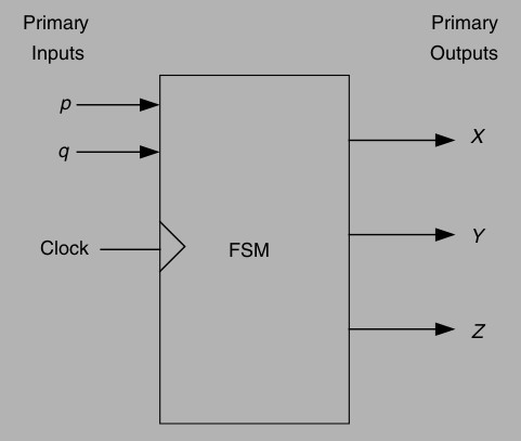
Some FSMs have a clock input and are called synchronous FSMs, i.e. those that do not belong to a type of FSM called asynchronous FSMs. Each state of the FSM needs to be identifiable. This is achieved by using a number of internal (to the FSM block) flip-flops. An FSM with four states would require two flip-flops, since two flip-flops can store 22 =4 state numbers. Each state has a unique state number, and states are usually assigned numbers as s0 (state 0), s1, s2, and s3 (for the four-state example). The rule here is
Number of states = 2(number of flip-flops) or Number of flip-flops = log2(number of states)
State Table
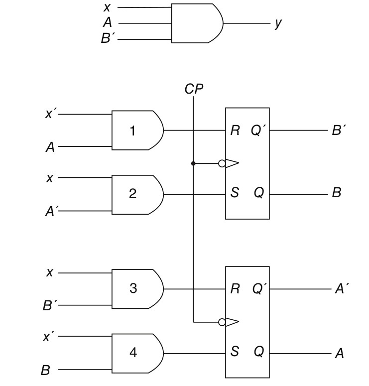
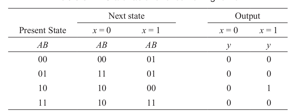
The time sequence of inputs, outputs, and flip-flop states may be enumerated in a state table. The state table for the circuit of Fig. 1.2 is shown in Table 1.1. It consists of three sections labeled present state, next state, and output. The present state designates the states of flip-flops before the occurrence of a clock pulse. The next state shows the states of flip-flops after the application of a clock pulse, and the output section lists the values of the output variables during the present state. Both the next state and output sections have two columns, one for x = 0 and the other for x = 1.
State Equations
A state equation (also known as an application equation) is an algebraic expression that specifies the conditions for a flip-flop state transition. The left side of the equation denotes the next state of a flip-flop and the right side, a Boolean function that specifies the present state conditions that make the next state equal to 1. A state equation is similar in form to a flip-flop characteristic equation, except that it specifies the next state conditions in terms of external input variables and other flip-flop values. The state equation is derived directly from a state table. For example, the state equation for flip-flop A is derived from inspection of Table 1-1. From the next state columns, we note that flip- flop A goes to the 1 state four times: when x = 0 and AB = 01 or 10 or 11, or when x = 1 and AB = 11. This can be expressed algebraically in a state equation as follows:
A(t + 1) = (A′B + AB′ + AB) x′ + Abx
State Diagram
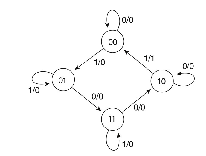
The information available in a state table may be represented graphically in a state diagram. In this diagram, a state is represented by a circle, and the transition between states is indicated by directed lines connecting the circles. The state diagram of the sequential circuit give in the Section 1.1 is shown below. The binary number inside each circle identifies the state the circle represents. The directed lines are labeled with two binary numbers separated by a /. The input value that causes the state transition is labeled first; the number after the symbol / gives the value of the output during the present state. For example, the directed line from state 00 to 01 is labeled 1/0, meaning that the sequential circuit is in a present state 00 while x = 1 and x = 0, and that on the termination of the next clock pulse, the circuit goes to next state 01. A directed line connecting a circle with itself indicates that no change of state occurs. The state diagram provides the same information as the state table and is obtained directly from table in Section 1.1
Types of Finite State Machines:
Mealy Model
n this model, the FSM has a number of inputs that connect to the Next State Decoder (combinational) logic. The Q outputs of the memory element Flip- Flops connect to the Output Decoder logic, which in turn connects to the Outside World Outputs. The Flip-Flops outputs are used as Next State inputs to the Next State Decoder, and it is these that determine the next state that the FSM will move to. Once the FSM has moved to this Next State, its Flip-Flops acquire a new Present State, as dictated by the Next State Decoder. Note that some of the Outside World Inputs connect directly to the Output Decoder logic. This is the main feature of the Mealy-type FSM.
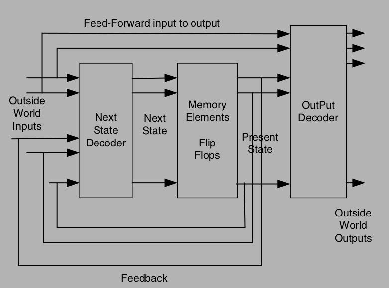
Moore Model
Another architectural form for an FSM is the Moore FSM. The Moore FSM Section 2.2 differs from the Mealy FSM in that it does not have the feed-forward paths. This type of FSM is very common. Note that the Outside World Outputs are a function of the Flip-Flops outputs only (unlike the Mealy FSM architecture, where the Outside World Outputs are a function of Flip-Flops outputs and some Outside World Inputs).
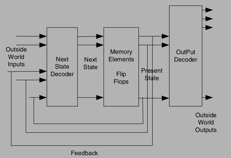
Pre-Requisite Verilog Commands:
Initial
A set of Verilog statements are usually executed sequentially in a simulation. These statements are placed inside a procedural block. Initial is one of the two main types of procedural block statements. An initial block is not synthesizable and hence cannot be converted into a hardware schematic with digital elements. Hence initial blocks do not serve much purpose than to be used in simulations. These blocks are primarily used to initialize variables and drive design ports with specific values.This block will be executed only once during the entire simulation. Execution of an initial block finishes once all the statements within the block are executed.
The syntax is shown below:
initial
  [single statement]

initial begin
  [multiple statement]
end
Always
An always block is one of the procedural blocks in Verilog. Statements inside an always block are executed sequentially. The always block is executed at some particular event defined in the sensitivity list. A sensitivity list is the expression that defines when the always block should be executed and is specified after the @ operator within parentheses ( ) . This list may contain either one or a group of signals whose value change will execute the always block. An always block can be used to realize combinational or sequential elements. A sequential element like flip flop becomes active when it is provided with a clock and reset. Similarly, a combinational block becomes active when one of its nput values change. These hardware blocks are all working concurrently independent of each other. The connection between each is what determines the flow of data. To model this behavior, an always block is made as a continuous process that gets triggered and performs some action when a signal within the sensitivity list becomes active. The syntax is displayed in Section 2.2
always @ (event)
  [statement]

always @ (event) begin
  [multiple statement]
end
Begin..End
Statements are wrapped using begin and end keywords and will be executed sequentially in the given order, one after the other. Delay values are treated relative to the time of execution of the previous statement. After all the statements within the block are executed control may be passed elsewhere. The syntax is shown in Section 3.3
begin : name_seq
  [statements]
end
Fork..Join
Statements are launched in parallel by wrapping them within the join and fork keywords. A parallel block can execute statements concurrently and delay control can be used to provide time-ordering of the assignments. The syntax is shown in Section 3.4
fork : name_fork
  [statements]
join
Blocking Statements
Blocking assignment statements are assigned using = and are executed one after the other in a procedural block. However, this will not prevent execution of statments that run in a parallel block. For eg
module tb;
  reg[7:0] a, b, c, d, e;

  initial begin
    a = 8'hDA;
    $display("[%0t] a=0x%0h b=0x0%h c=0x0%h", $time);

    b = 8'hF1;
    $display("[%0t] a=0x%0h b=0x0%h c=0x0%h", $time);

    c = 8'h30
    $display("[%0t] a=0x%0h b=0x0%h c=0x0%h", $time);
  end

  initial begin
    d = 8'hAA;
    $display("[%0t] d=0x0%h e=0x0%h", $time, d, e);

    e = 8'h55;
    $display("[%0t] d=0x0%h e=0x0%h", $time, d, e);
  end
endmodule
In the above example, there are two initial blocks which are executed in parallel when simulation starts. Statements are executed sequentially in each block and both blocks finish at time 0ns. To be more specific, variable a gets assigned first, followed by the display statement which is then followed by all other statements.
Non-Blocking Statements
Non-blocking assignment allows assignments to be scheduled without blocking the execution of following statements and is specified by a <= symbol. It's interesting to note that the same symbol is used as a relational operator in expressions, and as an assignment operator in the context of a non-blocking assignment. The following code snippet is written by replacing all the blocking statements in the previous example by non blocking statements. Try out for yourself and compare the difference in the outputs 😃 .
module tb;
  reg[7:0] a, b, c, d, e;

  initial begin
    a <= 8'hDA;
    $display("[%0t] a=0x%0h b=0x0%h c=0x0%h", $time);

    b <= 8'hF1;
    $display("[%0t] a=0x%0h b=0x0%h c=0x0%h", $time);

    c <= 8'h30
    $display("[%0t] a=0x%0h b=0x0%h c=0x0%h", $time);
  end

  initial begin
    d <= 8'hAA;
    $display("[%0t] d=0x0%h e=0x0%h", $time, d, e);

    e <= 8'h55;
    $display("[%0t] d=0x0%h e=0x0%h", $time, d, e);
  end
endmodule
Posedge and Negedge
Simply speaking, posedge means the transition from 0 to 1 negedge the oposit transition from 1 to 0 In synchronous sequential circuits, changes in flip-flops occur only in response to a transition of a clock pulse. The transition may be either a positive edge or a negative edge of the clock, but not both. Verilog HDL takes care of these conditions by providing these two keywords viz. posedge and negedge. The syntax is shown in Section 3.7
always@(posedge clock, negedge reset);Case Statement
The case statement checks if the given expression matches one of the other expressions in the list and branches accordingly. It is typically used to implement a multiplexer. The if-else construct may not be suitable if there are many conditions to be checked and would synthesize into a priority encoder instead of a multiplexer.
// Here 'expression' should match one of the lines
case(<expression>)
  case_item1  : <single statement>
  case_item2,
  case_item3  : begin
                <multiple statement>
              end
  default     : <statement>
endcase
The syntax is shown in Section 3.8. A Verilog case statement starts with the keyword case and ends with the endcase keyword. The expression within parantheses will be evaluated exactly once and is compared with the list of alternatives in the order they are written and the statements for which the alternative matches the given expression are executed. A block of multiple statements must be grouped and be within begin and end. If none of the case items match the given expression, statements within the default item is executed. The statement is optional, and there can be only one default statement in a case statement.
Examples of Implementing State Machines in Verilog:
Now that we are all set and armed with the required amunition of verilog commands, let’s dive headfirst into implementing state machines using verilog. This section will consist of four examples. Each example will consist of the problem statement, the state diagram, the verilog code and testbench and finally,the output of the code. Try implementing these problems on your own first without referring to this manual. If yoou get stuck at any point, you can come back and take a peek 😉 Remember, the key lies in understanding the state diagram thoroughly!!
Mealy Machine Implementations
Let’s start our dive with a simple example of implementing a mealy machine. Recall that in a Mealy machine, the output is a function of both, the present state as well as the input. Let’s consider the example of a Mealy Zero Detector shown in Section 4.1
Verilog Code:
module mealy_zero_det(
  output reg y_out,
  input x_in,clk,reset);

  reg [1:0] state,next_state;
  parameter S0 = 2'b00, S1 = 2'b01, S2 = 2'b10, S3 = 2'b11;

  always@(posedge clk,negedge reset)
    if (reset==0) state <= S0;
    else state<=next_state;

  always @ (state, x_in)
    case (state)
      S0:
        if (x_in) next_state = S1; else next_state =S0;
      S1:
        if (x_in) next_state = S3; else next_state =S0;
      S2:
        if (~x_in) next_state = S0; else next_state = S2
      S3:
        if (x_in) next_state = S2; else next_state=S0
    endcase

  always @ (state, x_in)
    case (state)
      S0:
        y_out = 0;
      S1, S2, S3:
        y_out = ~x_in;
    endcase

endmodule
TestBench:
module mealy_zero_det_tb();
  wire t_y_out;
  reg t_x_in,t_clock,t_reset;
  mealy_zero_det uut(t_y_out,t_x_in,t_clock,t_reset);initial #200 $finish;
  initial
    begin
      $dumpfile("dump.vcd");
      $dumpvars(1);
      t_clock = 0;
      forever #5 t_clock = ~t_clock;
    end
  initial
    fork
      t_reset = 0;
      #2 t_reset = 1;
      #87 t_reset = 0;
      #89 t_reset = 1;
      #10 t_x_in = 1;
      #30 t_x_in = 0;
      #40 t_x_in = 1;
      #50 t_x_in = 0;
      #52 t_x_in = 1;
      #54 t_x_in = 0;
      #70 t_x_in = 1;
      #80 t_x_in = 1;
      #70 t_x_in = 0;
      #90 t_x_in = 1;
      #100 t_x_in = 0;
      #120 t_x_in = 1;
      #160 t_x_in = 0;
      #170 t_x_in = 1;
    join
endmodule
Simulation Waveform:

Moore Machine Implememtation
Let’s try implementing the above example in Moore Model. The state diagram needs to be modified as in the Moore Model, the output depends only on the initial state. The state diagram will be as shown in Section 4.2
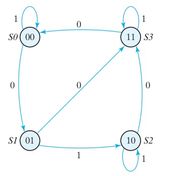
Verilog Code:
module moore_zero_det (
  output [1:0] y_out,
  input x_in, clock, reset
  );

  reg [1:0] state;
  parameter S0 = 2'b00, S1 = 2'b01, S2 = 2'b10, S3 = 2'b11;

  always @ (posedge clock, negedge reset)
    if (reset == 0)
      state <= S0;
    else
      case (state)
        S0:
          if (~x_in)
            state <= S1;
          else
            state <= S0;
        S1:
          if (x_in)
            state <= S2;
          else
            state <= S3;
        S2:
          if (~x_in)
            state <= S3;
          else
            state <= S2;
        S3:
          if (~x_in)
            state <= S0;
          else
            state <= S3;
      endcase

  assign y_out = state;
endmodule
Testbench:
module moore_zero_det_tb();
wire [1:0] t_y_out;
reg t_x_in,t_clock,t_reset;
moore_zero_det uut(t_y_out,t_x_in,t_clock,t_reset);initial #200 $finish;
initial
  begin
    // Dump waves
    $dumpfile("dump.vcd");
    $dumpvars(1);
    t_clock = 0;
    forever #5 t_clock = ~t_clock;
  end
    initial
      fork
        t_reset = 0;
        #2 t_reset = 1;
        #87 t_reset = 0;
        #89 t_reset = 1;
        #10 t_x_in = 1;
        #30 t_x_in = 0;
        #40 t_x_in = 1;
        #50 t_x_in = 0;
        #52 t_x_in = 1;
        #54 t_x_in = 0;
        #70 t_x_in = 1;
        #80 t_x_in = 1;
        #70 t_x_in = 0;
        #90 t_x_in = 1;
        #100 t_x_in = 0;
        #120 t_x_in = 1;
        #160 t_x_in = 0;
        #170 t_x_in = 1;
      join
endmodule
Simulation Waveform:

Chess Clock Controller
Background: At the start of a new game, the Reset input is asserted to initialize the system and clear both timers to zero time. This is achieved by means of the Clr output of the Chess Clock FSM being driven high, thereby asserting the reset (rst) input of both timers. Each chess player has a push-button, which when pressed applies a logic 1 to their respective inputs, Pa and Pb, of the Chess Clock FSM. After resetting the timers, the player who is not making the first move presses their push-button in order to enable the other player’s timer to commence timing.
For example, if Player-A is to make the first move, then Player-B starts the game by pressing their push-button. This has the effect of activating the Ta output of the Chess Clock FSM block in order to enable TIMER-A to record the time taken by Player-A to make the first move. Once Player-A completes the first move, Player-A’s button is pressed in order to stop their own timer and start Player-B’s timer (Ta is negated and Tb is asserted)
The state diagram of this machine is given in Section 4.3
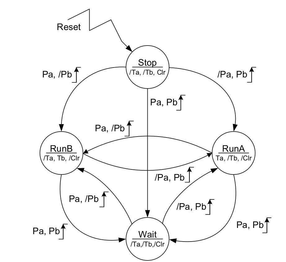
As shown, the FSM makes use of four states having the names shown in the upper half of the state circles. The states of the FSM outputs Ta, Tb and Clr are listed in the lower half of every state circle; those outputs preceded by ‘/’ are forced to logic 0, whereas those without ‘/’ are forced to logic 1. The presence of the output states within each of the state circles indicates that the Chess Clock FSM is of the Moore variety. The values of the inputs, Pa and Pb, are shown alongside each corresponding state transition path (arrow) using a format similar to that used to show the state of the outputs. The movement from one state to another occurs on the rising edge of the Clock input. Where the number of transitions shown originating from a given state is less than the total number possible, the remaining input conditions result in a so-called sling, i.e. the next state is the same as the current state.
Verilog Code:
module chess_clk_cntrl(
  output time_a,time_b,clr,
  input player_a,player_b,clk,reset);

  localparam run_a=0,run_b=1,stop=2,Wait=3;
  reg [1:0] state;
  always@(posedge clk,posedge reset)
    begin
      if(reset)
        state<=stop;
      else
        case(state)
          run_a:
            casex({player_a,player_b})
              2'b0x: state<=run_a;
              2'b10: state<=run_b;
              2'b11: state<=Wait;
            endcase
          run_b:
            casex({player_a,player_b})
              2'bx0: state<=run_b;
              2'b01: state<=run_a;
              2'b11: state<=Wait;
            endcase
          stop:
            case({player_a,player_b})
              2'b00: state<=stop;
              2'b01: state<=run_a;
              2'b10: state<=run_b;
              2'b11: state<=Wait;
            endcase
          Wait:
            if(player_a==player_b)
              state<=Wait;
          	else
              if(player_a==1'b1)
                state<=run_b;
          	  else
                state<=run_a;
        endcase
    end
  assign time_a=state==run_a;
  assign time_b=state==run_b;
  assign clr=state==stop;
endmodule
Testbench:
module chess_clk_cntrl_tb();
  wire time_a,time_b,clr;
  reg player_a,player_b,clk,reset;
  chess_clk_cntrl 	uut(time_a,time_b,clr,player_a,player_b,clk,reset);
  initial
    begin
      $dumpfile("dump.vcd");
	  $dumpvars(1);
      clk=1'b0;
      forever
        #50 clk=~clk;
    end

  initial
    begin
      reset=1'b1;player_a=1'b0;player_b=1'b0;
      #100 reset=1'b0;
      #101 player_a=1'b1;
      #167 player_a=1'b0;
      #215 player_b=1'b1;
      #289 player_b=1'b0;
      #350 player_a=1'b1;player_b=1'b1;
      #478 player_a=1'b0;player_b=1'b0;
      #513 player_b=1'b1;
      #550 $stop;
    end
endmodule
Simulation Waveform:

Vending Machine
Our vending machine is based on the following state diagram:
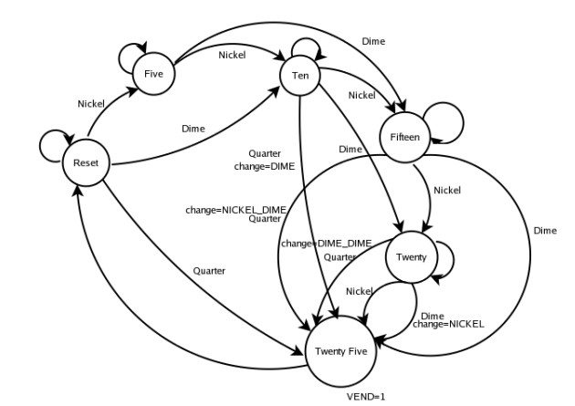
The machine has the following states: •State 1: Reset •State 2: Five •State 3: Ten •State 4: Fifteen •State 5: Twenty •State 6: Twenty Five The machine only accepts the following coins •Rs. 5 (nickel) •Rs. 10 (dime) •Rs. 25 (quarter) Whenever we get a coin we jump to the next state. So for example, if we get a coin from the reset state, say a Rs. 5 coin, then we jump to the next state Five . Otherwise we stay in the same state. When we get Extra amount we come back to the reset state and the difference is given back to the user.
Verilog Code
module vending_machine(
  output reg vend,
  output reg [2:0] change,state,
  input [2:0] coin,
  input clk,rst);

  parameter [2:0]rs_5= 3'b001;
  parameter [2:0]rs_10= 3'b010;
  parameter [2:0]rs_15= 3'b011;
  parameter [2:0]rs_20= 3'b100;
  parameter [2:0]rs_25= 3'b101;

  parameter [2:0]idle= 3'b000;
  parameter [2:0]five= 3'b001;
  parameter [2:0]ten= 3'b010;
  parameter [2:0]fifteen= 3'b011;
  parameter [2:0]twenty= 3'b100;
  parameter [2:0]twenty_five=3'b101;

  reg[2:0] next_state;

  always@(coin or state)
    begin
      next_state=0;
      case(state)
        idle:
          case(coin)
            rs_5: next_state=five;
            rs_10: next_state=ten;
            rs_25: next_state=twenty_five;
            default: next_state=idle;
          endcase
        five:
          case(coin)
            rs_5: next_state= ten;
            rs_10: next_state=fifteen;
            rs_25: next_state=twenty_five;
            default: next_state=five;
          endcase
        ten:
          case(coin)
            rs_5: next_state=fifteen;
            rs_10: next_state=twenty;
            rs_25: next_state=twenty_five;
            default: next_state=ten;
          endcase
        fifteen:
          case(coin)
            rs_5: next_state=twenty;
            rs_10: next_state=twenty_five;
            rs_25: next_state=twenty_five;
            default: next_state=fifteen;
          endcase
        twenty:
          case(coin)
            rs_5: next_state=twenty_five;
            rs_10: next_state=twenty_five;
            rs_25: next_state=twenty_five;
            default: next_state=twenty;
          endcase
        twenty_five:
          next_state=idle;
        default: next_state=idle;
      endcase
    end

  always@(clk)
    begin
      if(rst)
        begin
          change<=3'b000;
          vend<=1'b0;
          state<=idle;
        end
      else
        state<=next_state;
      case(state)
        idle:
          begin
            vend<=1'b0;
            change<=3'd0;
          end
        five:
          begin
            vend<=1'b0;
            if(coin==rs_25)
              change<=rs_5;
            else
              change<=3'd0;
          end
        ten:
          begin
            vend<=1'b0;
            if(coin==rs_25)
              change<=rs_10;
            else
              change<=3'd0;
          end
        fifteen:
          begin
            vend<=1'b0;
            if(coin==rs_25)
              change<=rs_15;
            else
              change<=3'd0;
          end
        twenty:
          begin
            vend<=1'b0;
            if(coin==rs_10)
              change<=rs_5;
            else
              if(coin==rs_25)
                change<=rs_20;
              else
                change<=3'd0;
          end
        twenty_five:
          begin
            vend<=1'b1;
            change<=3'd0;
          end
        default: state<=idle;
      endcase
    end
endmodule
TestBench:
module vending_machine_tb();
  wire vend;
  wire [2:0] change,state;
  reg [2:0] coin;
  reg clk,rst;

  vending_machine uut(vend,change,state,coin,clk,rst);

  parameter [2:0]rs_5= 3'b001;
  parameter [2:0]rs_10= 3'b010;
  parameter [2:0]rs_15= 3'b011;
  parameter [2:0]rs_20= 3'b100;
  parameter [2:0]rs_25= 3'b101;

  parameter [2:0]idle= 3'b000;
  parameter [2:0]five= 3'b001;
  parameter [2:0]ten= 3'b010;
  parameter [2:0]fifteen= 3'b011;
  parameter [2:0]twenty= 3'b100;
  parameter [2:0]twenty_five=3'b101;

  initial
    begin
    $dumpvars;
	  $dumpfile("file.vcd");
      clk=1'b0; rst=1'b1;
      #2 rst=0; coin=rs_5;
      #2 rst=1; coin=2'b00;
      #2 rst=0;coin=rs_10;
      #2 rst=1; coin=2'b00;
	  #2 rst=0; coin=rs_25;
      #2 rst=1; coin=2'b00;
      #2 rst=0; coin=rs_5;
      #2 coin=rs_5;
      #2 coin=rs_5;
      #2 coin=rs_5;
      #2 coin=rs_5;
      #2 rst=1; coin=2'b00;
      #2 rst=0; coin=rs_5;
      #2 coin=rs_10;
      #2 coin=rs_10;
      #2 rst=1; coin=2'b00;
      #2 rst=0; coin=rs_10;
      #2 coin=rs_25;
      #2 coin=rs_5;
      #2 rst=1; coin=2'b00;
      #2 rst=0; coin=rs_10;
      #2 coin= rs_10;
      #2 coin=rs_25;
      #2 rst=1; coin=2'b00;
      #2 $finish;
    end
  always
	#1 clk=~clk;
  initial
    begin
      if (rst)
			coin=2'b00;
	end
endmodule
And with this we have come to the end of the manual for Finite State Machines. Up next, you will learning the implementation of a Single Cycle MIPS Processor. Hopefully this manual helped in broadening your understanding of Finite State Machines from a very basic to a fairly advanced level. You’ll be required to implement these concepts again in the Practice Questions.
References
- Digital Design: With An Introduction to Verilog HDL (5th Edition), M. Morris Mano, Michael D. Cilleti.
- FSM-based Digital Design using Verilog HDL, Peter Minns and Ian Elliott.
- http://www.csun.edu/~ags55111/
- [https://ocw.mit.edu/courses/6-111-introductory-digital-systems-
laboratory-spring-2006/](https://ocw.mit.edu/courses/6-111-introductory-digital-systems-
laboratory-spring-2006/) - https://www.chipverify.com/verilog/verilog-tutorial
